Manual
About
ZL Equalizer is an equalizer plugin with the following key features:
- Multiple Filter Settings: Supports 6 filter structures, 16 frequency bands, 8 filter types, 5 stereo modes, 7 variable slopes.
- High-Quality Sound: With 64-bit floating-point processing and de-cramping technique, outstanding performance is ensured in both low-end and high-end.
- Adjustable Dynamics: Adjustable threshold, attack, release, and side-chain frequency, etc.
- Carefully Designed Interface: Interactive spectrum graph, smart collision detection, and smooth animations.
Components
Button
Click the button to switch between the “pressed” and “released” states.
Rotary/Horizontal/Vertical Slider
You can adjust values by clicking/dragging the left button of the mouse or scrolling the mouse wheel. For rotary sliders, you can modify the way the mouse dragging works.
You can reset values to the defaults or open the value editor by double-clicking the mouse. For more details, see UI Control Settings. To avoid changing the original value, you can double-click the right button of the mouse.
Top Panel

![]()
You can open the UI setting panel by double-clicking the logo. You can reset the window size by double-clicking the logo with Ctrl/Command.
Match Setting
You can open the match analyzer and the match control panel by clicking Match and close them by clicking Match again.
When those two panels are visible, you cannot interact with the spectrum, and the left panel and right panel are hidden. At the same time, the refresh rate will be halved to reduce rendering pressure.
Input/Target/Difference curves are kept alive only when those two panels are visible. Once you close those two panels (by clicking Match) or close the plugin window, the curves will get reset.
For more information, please refer to Equalization Match.
General Setting
You can open the general setting panel by clicking General and close it by clicking somewhere else.
The components of this setting panel are:
Filter Structure
Minimum Phase: Minimum PhaseState Variable: State VariableParallel: ParallelMatched Phase: Matched PhaseMixed Phase: Mixed PhaseLinear Phase: Linear Phase
Zero Latency (Zero LAT)
OFF: turn off zero latencyON: turn on zero latency- You can also click on the label on the left to switch options
When zero latency is on (and lookahead is zero), the extra latency is zero. However, the buffer size will slightly affect dynamic effects and parameter automation. The plugin will still have latency if the plugin is in
Matched Phase,Mixed Phase, orLinear Phase.
Collision Setting
You can open the collision detection setting panel by clicking Collision and close it by clicking somewhere else.
The components of this setting panel are:
Switch (DET)
OFF: turn off the collision detectionON: turn on the collision detection- You can also click on the label on the left to switch options
Detection (Strength)
- If you increase this parameter, the detected areas will become larger and darker
Detection (Scale)
- If you increase this parameter, the detected areas will become darker
Collision detection compares the main-chain signal and the side-chain signal in real-time.
Generally, it should only be used when the plugin uses an external side-chain signal. When the plugin uses the internal side-chain, collision areas can be perceived as the spectrum peaks of the main-chain signal.
Collision detection uses an independent spectrum graph, which is not affected by
Analyzersettings.When collision detection is activated, the frame rate of the
Main Panelwill decrease to reduce the rendering pressure.Collision detection may cause interface lag.
Dynamic Setting
You can open the dynamic detection setting panel by clicking Dynamic and close it by clicking somewhere else.
The components of this setting panel are:
Lookahead
- the delay of the main-chain signal
- when PDC is supported (hopefully in your DAW), it can be interpreted as the lookahead time of the side-chain signal
RMS
- the length of the audio when calculating the instantaneous loudness
- the actual attack/release will increase (significantly) when RMS increases
Smooth
- the smoothness of attack/release
High Quality (HQ)
- OFF: turn off the high-quality
- ON: turn on the high-quality
- You can also click on the label on the left to switch options
When high-quality is on, dynamic will adjust the filter state per sample, which smooths dynamic effects and reduces artifacts. However, high-quality will significantly increase the processing time of dynamic.
Analyzer Setting
You can open the analyzer setting panel by clicking Analyzer and close it by clicking somewhere else.
The components of this setting panel are:
FFT Mode
Pre,Post, andSiderepresents the input main-chain signal, the output main-chain signal, and the side-chain signalOFF: turn off the spectrumON: turn on the spectrumFRZ: freeze the spectrum- You can also click on the label on the left to switch options
Decay Speed
- applies to spectrums that is on (and not frozen)
Slope
- affects the spectrum display (not the actual signal)
0 dB/oct: no tilting, white noise displays as a horizon line3 dB/oct: pink noise displays as a horizon line4.5 dB/oct: default value, which represents perceived loudness better
Output Setting
You can open the output detection setting panel by clicking Output and close it by clicking somewhere else.
When Gain Tag Colour is not fully transparent, the summation of SGC, AGC, Output Gain and the Scale will show up per 1.5 second.
The components of this setting panel are:
Scale
The ratio of the actual gain over the displayed gain of all ‘gain type’ filters (Peak, Low Shelf, High Shelf, and Tilt Shelf) (including all base filters and target filters).

- Press: flip the phase of the output signal
- Release: don’t flip the phase

- Press: turn on Auto Gain Compensation
- Release: turn off Auto Gain Compensation
AGC calculates the difference between the loudness of the main-chain signal before/after filters and applies the corresponding gain. Therefore, AGC will affect the dynamic of the main-chain signal.
When AGC is on, the output main-chain signal will pass through a hard clipper at 0 dB.

- Press: when you press it, it starts to measure the integrated loudness of the input signal and the output signal
- Release: when you release it, it turns AGC off and updates the
Output Gainto the difference between two loudness values
Output Gain
Top-Right Buttons

- Press: turn on Static Gain Compensation
- Release: turn off Static Gain Compensation
SGC estimates the amount of compensation from filters’ parameters. SGC is inaccurate. However, it will NOT affect the dynamic of the main-chain signal.

- Press: use external side-chain
- Release: use internal side-chain

- Press: bypass the plugin
- Release: turn on the plugin
Bottom Panel
The bottom panel controls the parameters of the currently selected frequency band. Components will be introduced in the order from left to right, and from top to bottom.
Left Panel

- Press: solo the audio affected by the selected frequency band.
- Release: stop the solo.
Filter Type
There are a total of eight filter types: Peak, Low Shelf, Low Pass, High Shelf, High Pass, Notch, Band Pass, and Tilt Shelf.
Slope
There are seven slopes: 6 dB/oct, 12 dB/oct, 24 dB/oct, 36 dB/oct, 48 dB/oct, 72 dB/oct, and 96 dB/oct. A higher slope will make the filter’s response curve change more steeply. Peak, Notch, and Band Pass don’t support 6 dB/oct.
Stereo Modes
There are five stereo modes: Stereo, Left, Right, Mid, and Side.
Frequency (Freq)
Gain
When the dynamic feature is enabled, you can adjust the gain of the base filter by dragging/clicking with the left mouse button. To adjust the gain of the target filter, use the right mouse button for dragging/clicking. To adjust the gain of the base filter and the target filter, use the mousewheel.
Bandwidth (Q)
When the dynamic feature is enabled, you can adjust the Q value of the base filter by dragging/clicking with the left mouse button. For adjusting the Q value of the target filter, use the right mouse button for dragging/clicking. To adjust the Q values of the base filter and the target filter, use the mouse-wheel.
Band Selection
You can select the band by using the left arrows and right arrows.

- Press: turn on the dynamic effect for the selected frequency band.
- Release: turn off the dynamic effect for the selected frequency band.

- Press: enables automatic threshold for the selected frequency band.
- Release: disables automatic threshold for the selected frequency band and applies the learned threshold.

- Click: turns off the selected frequency band and resets all parameters to default values.
Right Panel
- Press: cancel the bypass
- Release: bypass the dynamic effect for the selected frequency band
- Press: solo the side-chain audio of the selected band
- Release: stop the solo

- Press: set the dynamic threshold to the relative mode
- Release: set the dynamic threshold to the absolute mode

- Press: swap the side-chain
- if the filter is in Left/Right, the side-chain is from Right/Left
- if the filter is in Mid/Side, the side-chain is from Side/Mid
Threshold
Knee Width (Knee)
The adjusted knee width value is within the range of 0 to 1, and the actual knee width is this value multiplied by 60 dB.
Attack
Release
Side-chain Bandpass Frequency (Freq)
Adjust the center frequency of the bandpass filter applied to the side-chain audio. When the dynamic effect is turned on, this frequency will be automatically adjusted to fit the audio affected by the main-chain filter.
Side-chain Bandpass Bandwidth (Q)
Adjust the Q value of the bandpass filter applied to the side-chain audio. When the dynamic effect is turned on, this Q value will be automatically adjusted to fit the audio affected by the main-chain filter.
Match Control Panel
Target Curve
There are three target curves:
Side: learned from the side-chain signal (to learn external side-chain signal, make sure you have enabled external side-chain in the top-right buttons)Preset: loaded from a preset file (.csvfile)Flat: set as a flat -4.5 dB/oct line
Weight
Adjust the loudness-weighting parameters of the curve learning model. The model will learn more from the louder signal if the weight is larger.

- Press: start the curve learning
- Release: pause the curve learning

- Click: save the current target curve as a preset file (
.csvfile)
Smooth
Adjust the smoothness of the difference curve. When 0 < Smooth < 0.5, you can increase the smoothness of the difference curve by increasing the value. When 0.5 < Smooth < 1, you can scale the difference curve by increasing the value.
Slope
Adjust the slope of the difference curve.
Fitting Algorithm Choice
LD: local gradient-based algorithm (fast)GN: global gradient-free algorithm (recommended)GN+: global gradient-free algorithm (slow, allows filters to have higher slopes)
- Click: start the fitting
Running will show up on the spectrum when the fitting is in progress.
Num Band
Adjust the number of bands used for fitting. When the fitting is completed, the curve fitting model will suggest the number of bands. You can change it afterward.
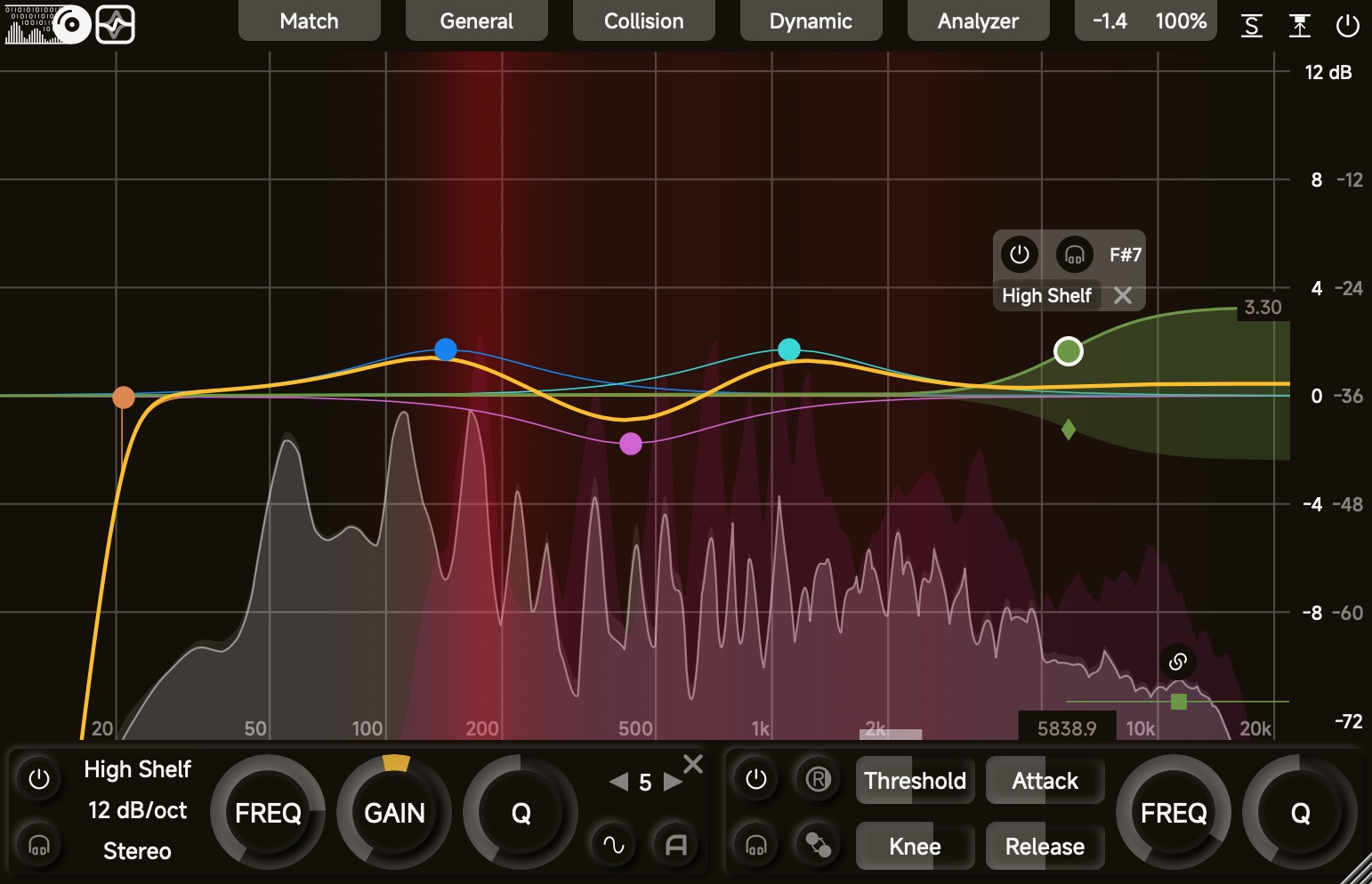
Main Panel
The main panel consists of grid lines, a spectrum graph, single frequency band response curves, an overall response curve, and a dB scale on the right side.
Add a Frequency Band
If there is at least one frequency band in the off state when you double-click the spectrum, a frequency band will be turned on with the corresponding frequency/gain:
- Frequency < 20Hz: Adds a High Pass filter.
- 20Hz <= Frequency < 50Hz: Adds a Low Shelf filter.
- 50Hz <= Frequency < 5000Hz: Adds a Peak filter.
- 5000Hz <= Frequency < 15000Hz: Adds a High Shelf filter.
- 15000Hz <= Frequency: Adds a Low Pass filter.
If you double-click the spectrum with Ctrl/Command, the dynamic of the new band will be turned on.
Drag a Frequency Band
When a frequency band is not in the off state, a draggable button appears at the corresponding frequency/gain position. You can adjust the frequency and gain by dragging the button, and adjust the Q value with your mouse wheel.
When you select the frequency band, the button will be highlighted, and an additional control window will appear. Through this window, you can quickly bypass/solo the selected band and adjust the filter type.
Additionally, if the dynamic function of this frequency band is not disabled:
- A draggable diamond-shaped button will appear at the corresponding position of the target filter, allowing you to adjust the frequency and gain of the target filter by dragging this button. After selecting it, you can adjust the Q value of the target filter by scrolling the mouse wheel.
- A draggable square-shaped button will appear at the corresponding position of the side-chain bandpass filter, enabling you to adjust the frequency of the bandpass filter by dragging this button. After selecting it, you can adjust the Q value of the bandpass filter by scrolling the mouse wheel.
- A dynamic link button will appear above the side-chain band-pass filter. You can enable/disable the dynamic link of that band by clicking this button.
When Filter Parameter Tags Colour is not fully transparent, the filter frequency/gain will appear as two tags on the spectrum.
Select Multiple Bands
You can use your mouse to drag and select multiple frequency bands simultaneously on the spectrum graph. After that, you can click on the spectrum graph (outside the button area) to cancel the selection.
When multiple frequency bands are selected, bypassing/turning off one frequency band or adjusting the frequency/gain/bandwidth of one frequency band will also affect the corresponding parameters of the other selected frequency bands.
Decibel Scale
You can choose the maximum decibel for the decibel scale. After that, the maximum gain of filters (when you drag buttons) is limited to that range.
Match Analyzer
When the match analyzer is visible, it will display three curves: the input curve (thin, in Pre Colour), the target curve (thin, in Side Colour), and the difference curve (thick, in the third colour of Colour Map 2).
The difference curve is displayed in the current decibel scale. The number of bands promoted by the fitting model is also affected by the current decibel scale.
There are also three draggable buttons:
- low-cut button: shows on the left and controls the low-frequency area ignored by the fitting model
- high-cut button: shows on the right and controls the high-frequency area ignored by the fitting model
- shift button: shows in the middle and controls the shift of the difference curve
You can also manually draw the difference curve:
- Command/Ctrl + left-mouse drag: draw the difference curve at the mouse position
- Command/Ctrl + Shift + left-mouse drag: set the difference curve to zero at the mouse position
- Command/Ctrl + right-mouse drag: reset the difference curve at the mouse position
- Shift + left-mouse double-click: reset the difference curve
UI Setting Panel
The UI setting panel controls spectrum colours, slider operations, etc. Components will be introduced in the order from top to bottom.
Colour
You can adjust the colour by clicking on the left colour block and change the transparency by dragging the right slider.
Text Colour
Background Colour
For better accessibility, please set Text/Background to colours with high contrast.
Shadow Colour
Glow Colour
Main-Chain Input Signal Spectrum Colour (Pre Colour)
Main-Chain Output Signal Spectrum Colour (Post Colour)
Side-Chain Signal Spectrum Colour (Side Colour)
Grid Lines Colour (Grid Colour)
Filter Parameter Tags Colour (Tag Colour)
Gain Tag Colour (Gain Colour)
Colour Map 1
- The colour map of the curves of each single filter.
Colour Map 2
- The colour map of the curves of Stereo/Left/Right/Mid/Side.
Import Colours
- import colour settings (
.xmlfile)
Export Colours
- export colour settings (
.xmlfile)
Control
Mouse-Wheel Sensitivity
- Rough: mouse-wheel sensitivity when Shift is not pressed
- Fine: mouse-wheel sensitivity when Shift is pressed
- Reverse: whether reverse the direction of mouse-wheel when Shift is pressed
Mouse-Drag Sensitivity
- Rough: mouse-drag sensitivity when Shift is not pressed
- Fine: mouse-drag sensitivity when Shift is pressed
Rotary Slider Style
Circular: A rotary control that you move by dragging the mouse in a circular motion, like a knobHorizontal: A rotary control that you move by dragging the mouse left-to-rightVertical: A rotary control that you move by dragging the mouse up-and-downHoriz + Vert: A rotary control that you move by dragging the mouse up-and-down or left-to-right- Distance: the relative distance that the mouse has to move to drag the slider across the full extent of its range. It does not apply to the Circular style.
Slider Double Click
Return Default: when you double-click the slider, it returns to the default value; when you double-click the slider with Ctrl/Command, it opens the value editor.Open Editor: when you double-click the slider, it opens the value editor; when you double-click the slider with Ctrl/Command, it returns to the default value.
Import Controls
- import control settings (
.xmlfile)
Export Controls
- export control settings (
.xmlfile)
Other
Rendering Engine
- The rendering engine used to render the user interface. By default, it is set as
Autoso that it can choose the best available rendering engine.
Refresh Rate
- The refresh rate of the response curve(s). The higher this value, the smoother the response curve(s) when dragging the buttons or enabling dynamic, but the higher the CPU and GPU load. When the CPU or GPU load is too high, the response curve may get distorted when dragging the button.
FFT Setting
- Tilt: the extra tilting slope of the FFT
- Speed: the extra decay speed of the FFT
- Resolution: resolution of the FFT (takes effect after restarting the DAW)
Higher resolution increases the low-frequency details of the spectrum with the cost of increasing computation on the background thread. Although it does not affect the audio thread, you may need to choose a lower resolution if the spectrum is lagging.
Curve Thickness
- Single: the thickness of the response curves of single bands
- Sum: the thickness of the overall response curves
Default Pass Filter Slope
Default Dynamic Link (Dyn Link)
OFF: turn off the default dynamic link (for bands of which the dynamic is enabled afterward, the dynamic link will be turned off by default)ON: turn on the default dynamic link (for bands of which the dynamic is enabled afterward, the dynamic link will be turned on by default)- You can also click on the label on the left to switch options
When the dynamic link for a band is on, adjusting the frequency or Q value of the main filter will correspondingly adjust the frequency or Q value of the side-chain band-pass filter. You can control the dynamic link of each band using the dynamic link button.
Tooltip
OFF: turn off tooltipsON: turn on tooltips- You can select the language through the right-hand pop-up menu. If
Systemis chosen, the plugin will attempt to use the system’s display language if possible.
Bottom Buttons
- Save the current setting.

- Load the default settings of some colours.
- Discard all unsaved settings and close the UI setting panel.
Shortcuts
Generally, you can enable fine-adjustment with Shift and enable special adjustment with Ctrl/Command. If the direction of mouse-wheel is reversed when Shift is pressed, you can reverse it again to put it back to normal.
- when using the mouse to drag / the mouse-wheel to adjust sliders, you can enable fine-adjustment with Shift
- when dragging the band button, you can enable fine-dragging with Shift
- when dragging the band button, you can fix frequency with Ctrl/Command + left-click and fix gain with Ctrl/Command + right-click
- you can add a dynamic band by double-clicking with Ctrl/Command
- you can turn on/off dynamic of a band by double-clicking with Ctrl/Command on the band button
Automation
You can automate frequency, gain, Q value, dynamic threshold, knee width, attack, and release parameters. Attention:
The modulation speed of automation is once per block. However, the filter parameters (
Freq,Gain, andQ) modulation changes filter states per sample.When the plugin window is open, filter parameter modulation may cause interface lag.
When you modulate multiple filters, DO NOT select them on the spectrum.
States of Bands
The frequency band can be in one of the following states:
- Off: By default, all frequency bands are closed, not affecting the spectrum graph, the overall response curve, or the audio signal.
- Bypassed: The response curve is displayed on the spectrum graph without affecting the overall response curve.
- On: The response curve is displayed on the spectrum graph and affects both the overall response curve and the audio signal.
Dynamic and Automatic Threshold
The dynamic effect calculates the instantaneous loudness of the side-chain (filtered by the bandpass filter) at a constant rate (not less than 1000 times per second) and adjusts the filter state as follows:
- When side-chain instantaneous loudness <= (threshold - knee width), the filter is in the base filter state.
- When side-chain instantaneous loudness >= (threshold + knee width), the filter is in the target filter state.
- When (threshold - knee width) < side-chain instantaneous loudness < (threshold + knee width), the filter parameters will be a mix of the baseline filter parameters and the target filter parameters with a proportion. And the filter state will be re-calculated. The closer the side-chain instantaneous loudness is to (threshold - knee width), the closer the filter state is to the baseline filter, and vice versa.
When automatic threshold is on, the plugin collects the side-chain’s instantaneous loudness and adjusts the threshold. The actual threshold is the automatic threshold + displayed threshold + 40.
When automatic threshold is turned off, the plugin sets the threshold to the median of the side-chain instantaneous loudness values and sets the knee width to half of the difference between the 95th and 5th percentiles.
When automatic threshold is off, the actual threshold is equal to the displayed threshold.
The threshold calculation is in the absolute mode by default. When the relative mode is activated, the dynamic effect will calculate the difference between the instantaneous loudness of the side-chain (filtered by the bandpass filter) and the overall instantaneous loudness of the side-chain. The threshold learning will work in the same mode.
Filter Structure
Minimum Phase
The most common filter structure of equalizers (Transposed-Direct-Form II). Low-order minimum phase filters (6 dB/oct and 12 dB/oct) cause small phase shifts. Therefore, when the signal processed by low-order minimum phase filters is mixed with the original or highly correlated signals, phase cancellation issues are almost inaudible. However, when frequency and gain are rapidly modulated, this type of filter is more likely to become unstable and produce audible artifacts.
State Variable
The most common filter structure of crossovers. This type of filter is more stable when frequency and gain are rapidly modulated. However, the phase shift caused by this type of filter is significant. It is not recommended to mix the processed signal with the original or highly correlated signals. What’s more, this type of filter will also affect the phase when it is bypassed.
Parallel
Under this filter structure, the Low Shelf (maximum 12 dB/oct) / High Sehlf (maximum 12 dB/oct) / Peak (maximum 24 dB/oct) filters are processed in Parallel while the remaining filters are still in Minimum Phase. For those parallel filters, the frequency response is DIFFERENT from the displayed curves. Besides that, Parallel filters perform dynamic processing in a different way, which is more efficient than Minimum Phase filters (especially under High Quality).
Matched Phase
All filters are still in Minimum Phase. Additionally, it uses a short FIR filter to match the magnitude/phase response of analog prototypes. This short FIR filter causes about 21 ms latency (up to about 64 ms if left/right or mid/side are used). I would advise against modulating parameters of filters with this structure.
Mixed Phase
All filters are still in Minimum Phase. Additionally, it uses a short FIR filter to match the magnitude response of analog prototypes and reduces phase shift at high-end. This short FIR filter causes about 43 ms latency (up to about 130 ms if left/right or mid/side are used). I would strongly advise against modulating parameters of filters with this structure.
Linear Phase
It has analog prototype magnitude response and zero phase response. This FIR filter causes about 171 ms latency (up to about 512 ms if left/right or mid/side are used). You should NOT modulate parameters of filters. Dynamic effect does not work.
Equalization Match
Equalization Match uses several filters to match the frequency spectrum of the input signal to the frequency spectrum of the target signal. The steps are listed as follows:
- Choose the target signal (learned from side-chain, loaded from presets, or set as flat).
- Start the learning. The curve learning model learns both the input signal and the side-chain signal. At the same time, it also calculates the difference between two signals. The difference is centered so that it is not affected by the loudness of the two signals. During this step, you can see three curves on the spectrum (input curve, target curve and difference curve). You may pause the learning when the difference curve becomes stable.
- Adjust the difference. Adjust the current difference curve by adjusting
Smooth, adjustingSlope, dragging the shift button, or drawing manually. - Start the fitting. The curve fitting model uses several filters to match the difference curves. Unless the computing resource is very limited, the
GNalgorithm is recommended. Once the fitting process is completed, the fitting model will set filter parameters. You may change the number of bands afterward.